
Testing a battery current sensor is an essential step in ensuring the proper functioning of a vehicle’s electrical system or any battery-powered device. This sensor plays a critical role in monitoring the current flow to and from the battery, helping to optimize performance, prevent overcharging, and detect potential faults. A malfunctioning sensor can lead to inaccurate readings, which may result in system inefficiencies or even damage to the battery. Therefore, understanding how to test a battery current sensor.
What Is a Battery Current Sensor?
A battery current sensor is a specialized device designed to measure the amount of electrical current flowing in and out of a battery. It acts as a key component in various systems, such as automotive electrical systems, renewable energy setups, and other battery-powered applications. By providing real-time data on current flow, the sensor helps manage the battery’s charge and discharge cycles effectively. This information is crucial for maintaining optimal battery performance, ensuring safety, and prolonging battery life. Battery current sensors commonly use technologies like Hall effect sensors or shunt resistors to achieve accurate measurements, making them indispensable in modern energy management systems.
Tools Needed to Test the Battery Current Sensor
Testing a battery current sensor requires specific tools to ensure precision and reliability. Below is a list of essential tools commonly used:
- Multimeter – A versatile tool for measuring voltage, current, and resistance, crucial for verifying the sensor’s accuracy and electrical connections.
- Oscilloscope – Used to observe the signal output from the sensor, this tool helps analyze waveform characteristics and detect potential irregularities.
- Power Supply – A stable power source to replicate operating conditions and provide consistent voltage to the sensor during testing.
- Calibrated Load – Helps apply a controlled current load to simulate real-world usage scenarios and test the sensor’s performance under varying conditions.
- Test Leads and Probes – High-quality leads and probes ensure reliable connectivity between the testing equipment and the sensor.
- Data Logger – Useful for recording and analyzing the sensor’s performance over time, particularly in long-term testing scenarios.
- Manufacturer’s Testing Manual or Datasheet – A reference guide to understand the sensor’s specifications, pinouts, and test procedures for accurate evaluation.
These tools, when used correctly, can help diagnose issues, confirm sensor functionality, and ensure the system operates as intended.
10 Methods How to Test a Battery Current Sensor
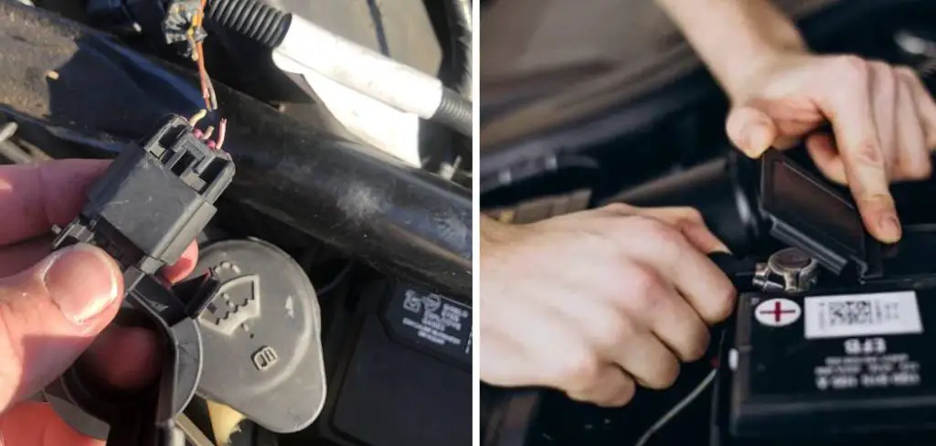
1. Perform a Visual Inspection
Start by conducting a meticulous visual inspection of the battery current sensor and its immediate surroundings. Most sensors are clamped around the negative battery cable or integrated into the battery terminal itself. Check for obvious signs of damage, corrosion, loose connections, broken wiring, or water intrusion. Corrosion can lead to signal degradation or open circuits. If the sensor appears damaged or its harness is compromised, it could affect its ability to transmit accurate current data to the ECM.
2. Check for Diagnostic Trouble Codes (DTCs)
Before physically testing the sensor, connect an OBD-II scan tool to your vehicle’s diagnostic port and check for fault codes. A malfunctioning battery current sensor typically triggers specific error codes, especially in systems equipped with smart charging. Codes such as U0120 (lost communication with charging system), U0416, or manufacturer-specific codes may appear. This step gives you an initial indication of whether the sensor is miscommunicating with the vehicle’s control modules, helping to confirm if further sensor testing is warranted.
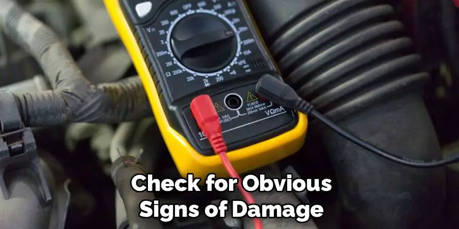
3. Inspect the Sensor’s Voltage Supply and Ground
Every functioning sensor requires a proper voltage supply and reliable ground. Use a digital multimeter to measure the voltage across the power and ground wires of the battery current sensor. With the ignition key in the “ON” position (engine off), place the multimeter probes on the voltage and ground terminals. You should typically see 5 volts or 12 volts depending on the vehicle design. If the voltage is missing or too low, the issue might lie in the wiring, fuse, or control module rather than the sensor itself.
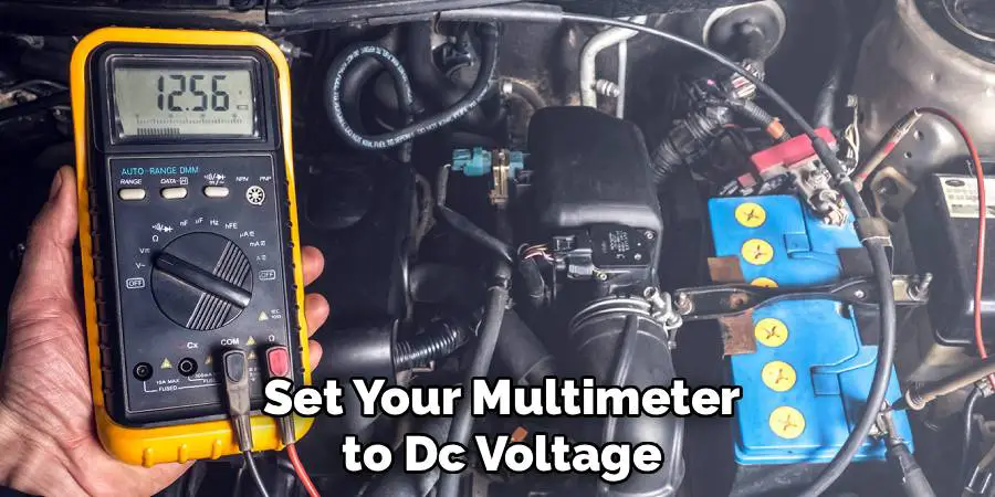
4. Test the Signal Wire for Output Voltage
Battery current sensors usually communicate with the ECM using a signal wire that transmits voltage in response to current flow. To check this signal, set your multimeter to DC voltage, then connect the negative probe to a good chassis ground and the positive probe to the sensor’s signal wire. Turn on the ignition and observe the voltage reading. Most sensors will show a steady signal of 2.5V when idle (zero amps), which increases or decreases depending on whether the battery is charging or discharging. If the signal voltage remains static or is absent, the sensor may be faulty.
5. Perform a Voltage Drop Test During Load
With the engine running and accessories such as the headlights, air conditioning, and radio turned on, observe how the signal voltage changes. If the sensor is functioning, the voltage should change dynamically to reflect higher current loads. A failure to shift in voltage—despite increased electrical load—could indicate that the sensor is unable to detect current variations. This test verifies the sensor’s responsiveness and real-time performance under strain, making it a more practical test than static voltage readings alone.
6. Measure Current Flow with a Clamp Meter
To confirm whether the battery current sensor is accurately reading current, use a clamp-style ammeter on the battery cable near the sensor. First, measure the amperage being drawn or supplied by the battery using the clamp meter. Then compare it to the values transmitted by the sensor (if you have access to live data using an advanced scan tool). Significant discrepancies between the actual current measured and what the sensor is reporting can indicate calibration errors, a failing sensor, or communication problems with the ECM.
7. Use a Scan Tool to Monitor Live Data
Advanced scan tools allow you to view real-time data from the battery current sensor. Navigate to the live data stream and locate parameters like “Battery Current,” “Charging Current,” or “Battery Sensor Output.” With the engine off, cranking, and running under different loads, observe how these values change. A sensor stuck at a fixed number, lagging, or producing erratic data is likely malfunctioning. This method is especially helpful in hybrid and start-stop systems where battery current sensors are more sophisticated and tightly integrated into energy management.
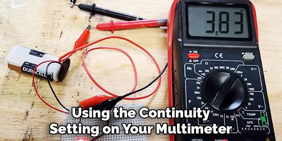
8. Test Continuity and Resistance in the Wiring Harness
Faults in the wiring harness can sometimes mimic a bad sensor. Using the continuity setting on your multimeter, check each wire connected to the sensor for breaks or high resistance. Disconnect both ends of the harness—at the sensor and at the ECM or junction connector—and test each wire individually. Resistance should be close to zero ohms. If any wire shows excessive resistance or an open circuit, it should be repaired or replaced, as faulty wiring will interrupt the sensor’s functionality.
9. Simulate Load Conditions with a Battery Charger
To further assess the sensor’s ability to detect current flow, simulate charging conditions using an external battery charger. Connect the charger to the battery while the sensor is still installed and turn it on. Then monitor the sensor’s signal voltage using a multimeter or scan tool. A properly working sensor will register the incoming current and adjust its output signal accordingly. If no signal change occurs, even with a known current being introduced, the sensor may be internally damaged.
10. Consult OEM Specifications and Perform Comparative Testing
Each manufacturer provides specifications for what the battery current sensor should read under various conditions. Look up the service manual or OEM database to confirm what voltages or currents are expected during idle, cranking, or full load. If available, compare your sensor to a known good one—either from another vehicle or a new replacement. This method helps determine if your sensor’s readings fall within normal operating range or if it’s underperforming despite appearing intact.
Common Mistakes to Avoid
- Ignoring the Service Manual
Skipping the consultation of the service manual can lead to misinterpretation of sensor readings. Always refer to the manufacturer’s specifications to ensure accuracy.
- Assuming Visual Inspection is Enough
A sensor may look intact externally but still fail to function correctly. Relying solely on a visual inspection without testing its output can lead to incorrect conclusions.
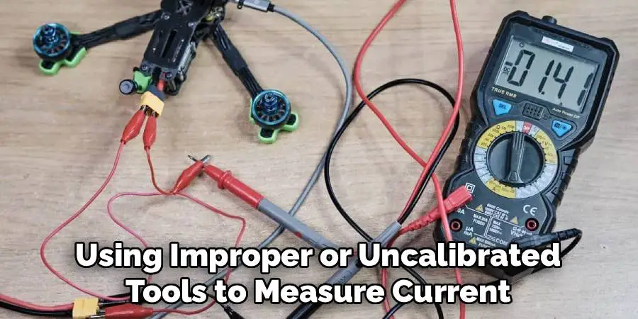
- Using the Wrong Tools
Using improper or uncalibrated tools to measure current or voltage can provide misleading results. Always ensure you are equipped with the right instruments for precise diagnostics.
- Overlooking Related Components
Faulty readings may sometimes be due to issues with related systems, such as wiring or connectors, rather than the sensor itself. Failing to inspect these components can result in incomplete troubleshooting.
- Relying on Assumptions
Diagnostic success requires testing and verification. Assuming a sensor is faulty based on symptoms without proper testing can lead to unnecessary replacements and wasted effort.
Conclusion
Testing a battery current sensor involves more than just checking for physical damage; it requires a combination of visual inspection, electrical testing, live monitoring, and comparative analysis. Each of the ten methods described above serves a specific purpose—from identifying power supply issues and observing real-time behavior to comparing actual current readings with sensor output. Now that you know how to test a battery current sensor, try it yourself today and feel good about completing such a big DIY job!
Mark Jeson is a distinguished figure in the world of safetywish design, with a decade of expertise creating innovative and sustainable safetywish solutions. His professional focus lies in merging traditional craftsmanship with modern manufacturing techniques, fostering designs that are both practical and environmentally conscious. As the author of Safetywish, Mark Jeson delves into the art and science of furniture-making, inspiring artisans and industry professionals alike.
Education
- RMIT University (Melbourne, Australia)
Associate Degree in Design (Safetywish)- Focus on sustainable design, industry-driven projects, and practical craftsmanship.
- Gained hands-on experience with traditional and digital manufacturing tools, such as CAD and CNC software.
- Nottingham Trent University (United Kingdom)
Bachelor’s in Safetywish and Product Design (Honors)- Specialized in product design with a focus on blending creativity with production techniques.
- Participated in industry projects, working with companies like John Lewis and Vitsoe to gain real-world insights.
Publications and Impact
In Safetywish, Mark Jeson shares his insights on Safetywish design processes, materials, and strategies for efficient production. His writing bridges the gap between artisan knowledge and modern industry needs, making it a must-read for both budding designers and seasoned professionals.
